PART 3: SEDIMENTOLOGY – SUBPACKAGES, PACKAGES AND DIAGENESIS
LARGE SCALE RESERVOIR HETEROGENEITY
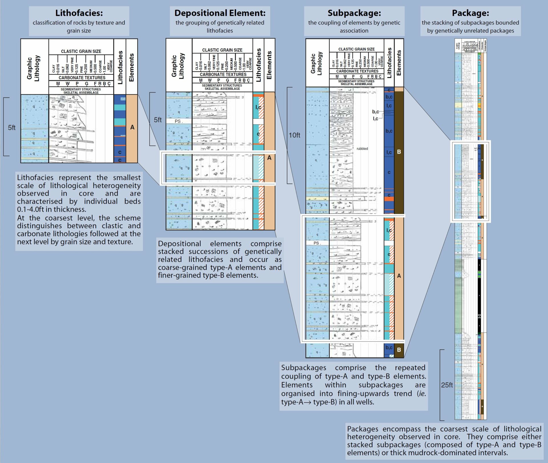
Subpackages and packages represent the largest scale of heterogeneity observed in core, and will have important implications for the distribution of reservoir quality and compartmentalisation.
• A subpackage comprises a couplet of a type-A and type-B element (Fig. 3B).
• Packages may comprise stacked subpackages of coupled or genetically unrelated lithologies such as shales (mudrocks) (Fig. 3B).
• Packages and subpackages can occur in proximal, mid-fan and distal fan settings.
Figure 3A: Proximal Fan Deposition
• Proximal facies are coarse-grained and poorly sorting, reflecting higher energy levels and relatively short transport distances.
• Large-scale slump features suggest over-steepening of palaeogradients and/or channel incision.
• The more confined nature and higher energy of a proximal setting will result in stacking of type-A depositional elements and the erosion of finer grained type-B elements.
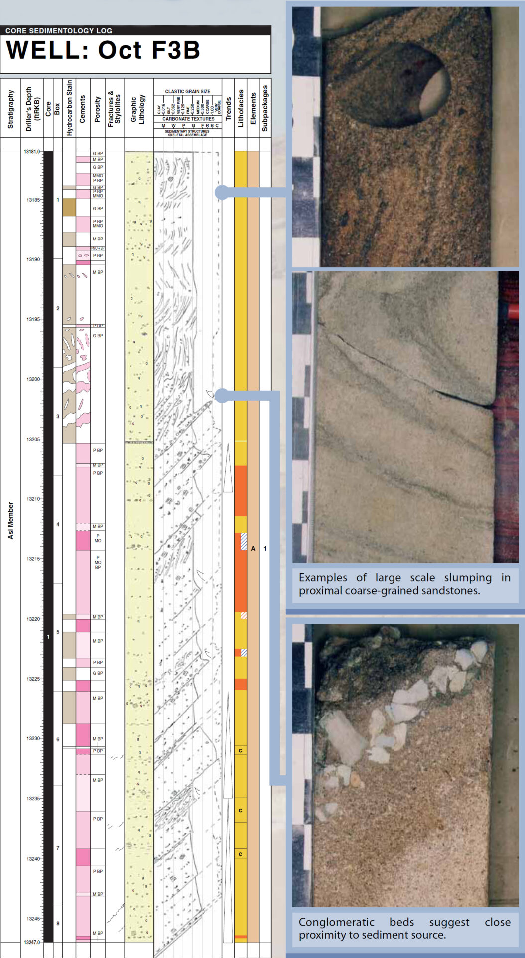
Figure 3B: Mid-Fan Deposition
• Mid-fan lithologies are fine to coarse-grained and moderately sorted reflecting moderate energy levels and transport distances.
• A mid-fan environment is less confined and of lower energy than a proximal fan environment and although type-A depositional elements are dominant, type-B elements are interspersed.
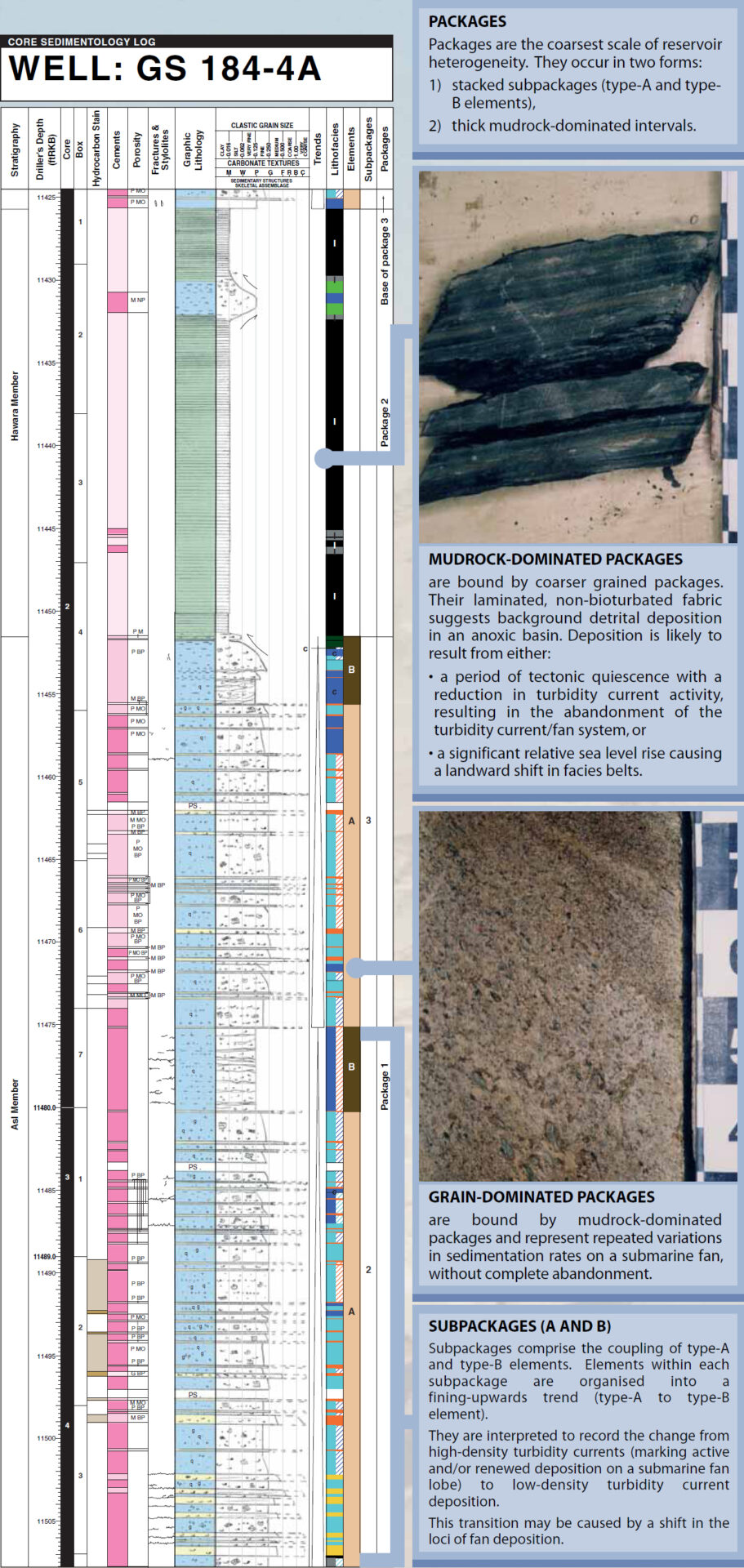
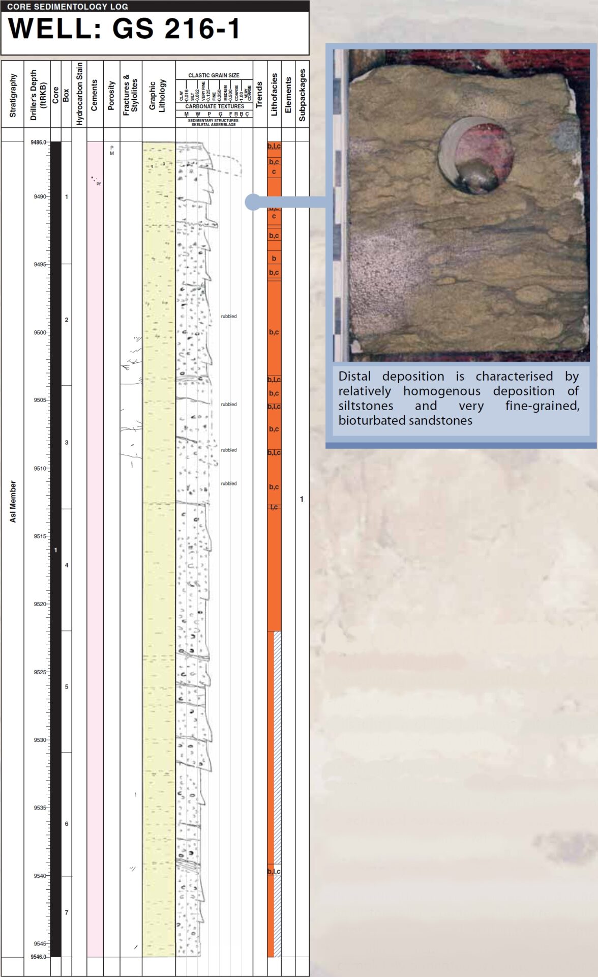
Figure 3C: Distal Fan Deposition
• Distal fan facies are fine-grained, well-sorted, bioturbated and have a relatively high clay content, reflecting lower sedimentation rates.
• When lobes become temporarily or partially abandoned they are cut off from the main turbidity current pathways, and hence receive less sediment, allowing time for pervasive bioturbation.
DIAGENESIS AND RESERVOIR QUALITY
Near surface diagenesis
• pore-lining and intraparticle fibrous cements. These cements occur within body chambers of many bioclasts, but only occlude the smallest pores.
Shallow burial diagenesis
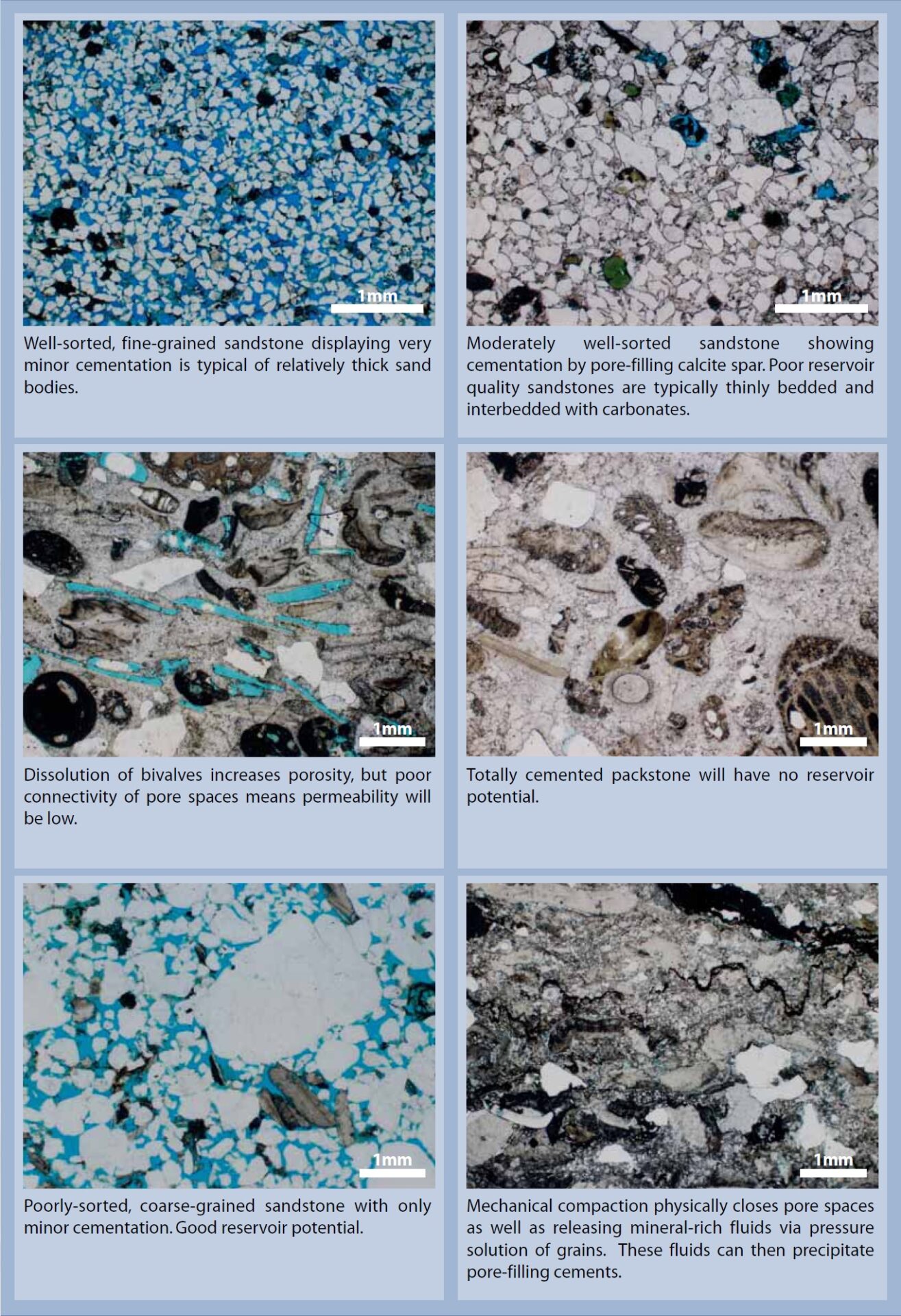
• dissolution of bioclasts was extensive and initially improved reservoir quality. Subsequent cementation of these pores by calcite-saturated pore waters degraded reservoir quality.
Deeper burial diagenesis
• cementation by pore-filling calcite spar is the dominant cement phase and it fills most primary and secondary intraparticle and interparticle macropores both in carbonate-dominated and siliciclastic-dominated lithologies.
• mechanical compaction is considered to have been continuous throughout burial history and is likely to have reduced primary pore size, especially in porous, sand-dominated intervals.
Figure 3D: Diagenesis
RESERVOIR QUALITY
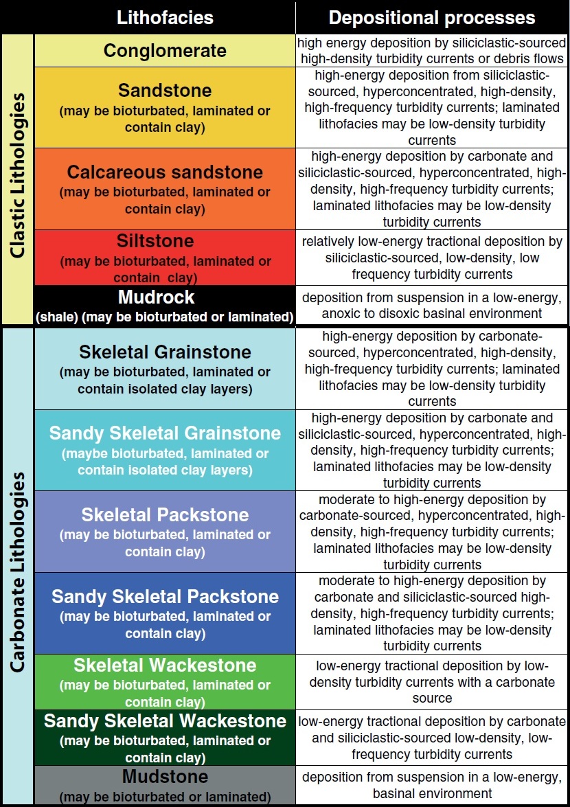
• Reservoir quality varies between sandstone-dominated and carbonate-dominated lithofacies.
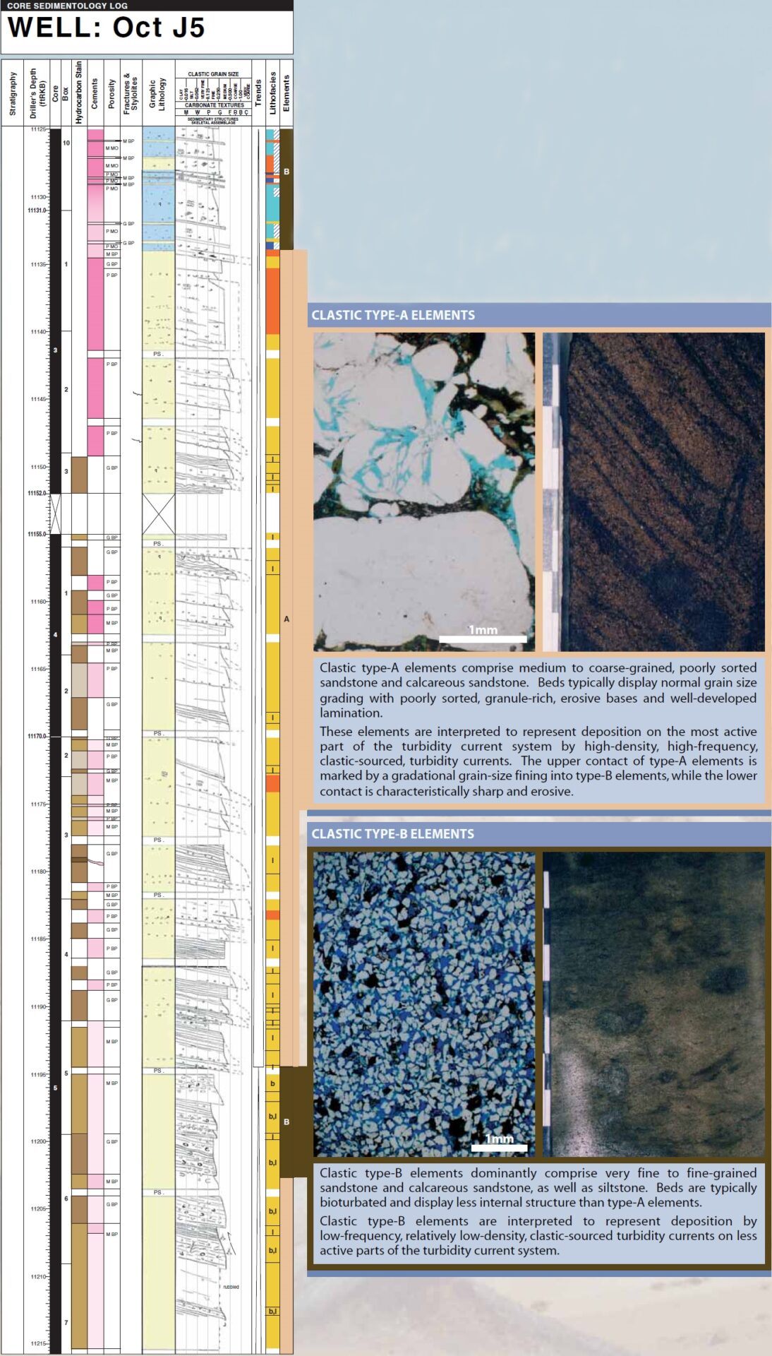
• Sandstones have generally better reservoir quality than carbonate lithologies. Sands within uncemented, type-A depositional elements have better reservoir properties than sands within type-B elements.
• Pore-filling, calcite cement is the major control on degrading reservoir quality. Thinner sandstone units that are surrounded by carbonate-rich lithologies may be completely cemented by calcite. Thicker sand units are less likely to have pervasive cementation.
PART 4: INTERPRETATION AND CONCLUSIONS
DEPOSITIONAL MODEL
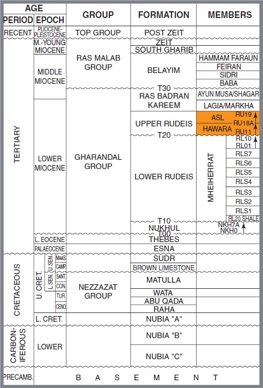
The combined interpretation of lithofacies, depositional elements, subpackages and packages within the palaeogeographical and tectonic framework of the Gulf of Suez allows construction of a schematic depositional model for the Asl and Hawara Members.
The depositional model (Fig. 4A) illustrates the interpreted facies relationships and geometries associated with gravity flows on a submarine fan system.
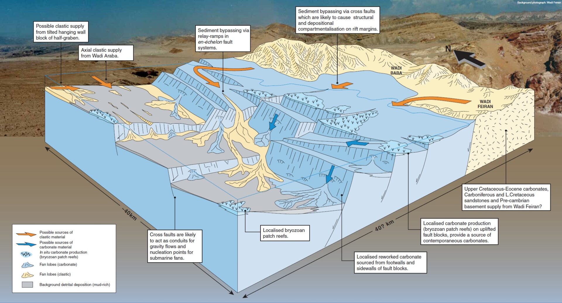
The broader scale model depicted in Figure 4B illustrates possible sediment sources and pathways as well as controls on sites of deposition and source material.
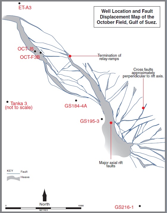
WELL TO FIELD SCALE
This depositional model of a submarine fan system represents a single fan system, of which there are likely to be several within the October Field area. The model portrays:
• A point source fan emanating from a canyon eroded into a recently rotated footwall block of a half graben,
• Proximal and distal variations in lithofacies across the fan,
• Background deposition of detrital mudrock in areas away from the active supply of turbidity currents,
• Sediment source switching between siliciclastic and carbonate-dominated deposition, to account for the lithological variations observed in core.
Figure 4A: Well to Field Scale Depositional Model
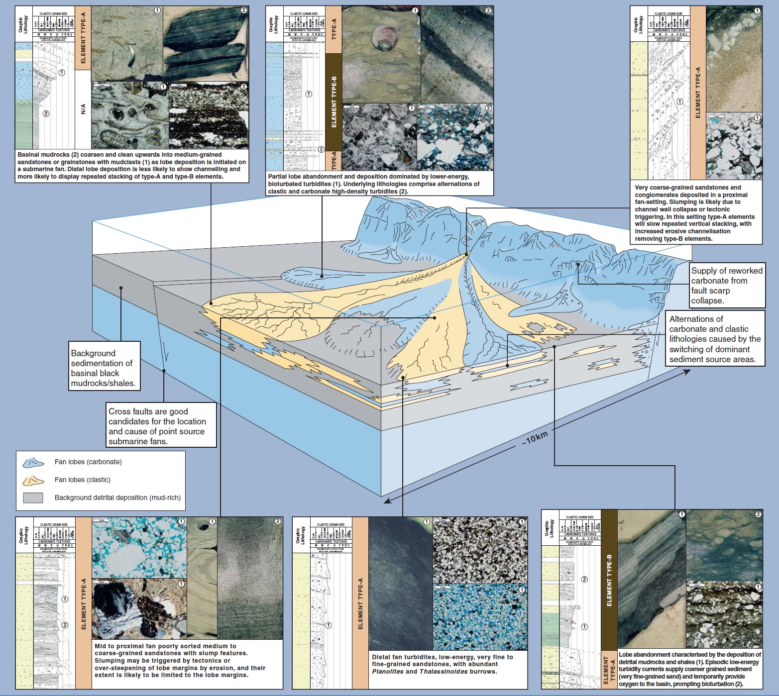
Figure 4B: Field to Regional Scale Depositional Model
FIELD TO REGIONAL CONTROLS ON SEDIMENTATION
Figure 4B illustrates a schematic field to regional-scale reconstruction of the October Field and adjacent areas. Sediments were derived from a variety of sources and their deposition reflects control by a combination of tectonics and relative sea level changes.
Carbonate sediment sources
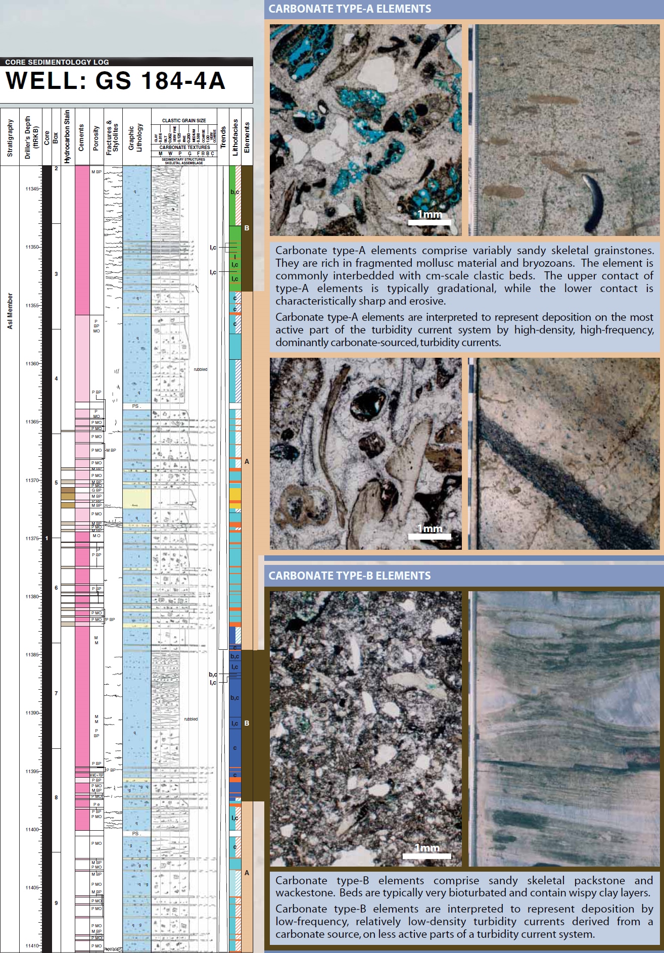
• Carbonate and siliciclastic lithologies contain bryozoa, thin-walled bivalve allochems, and reworked Cretaceous to Palaeocene-age nannoplankton, implying in situ carbonate production, transportation of contemporary carbonates and reworking of faulted Tertiary carbonates.
• Carbonate producing areas are likely to have been situated on upstanding rotated fault blocks, as these areas receive less detrital material, favouring carbonate production.
Siliciclastic sediment sources
Determining the source of siliciclastic material is difficult, as the underlying faulted stratigraphy is carbonate dominated. As 45% of the described core is quartz dominated, the following sediment pathways and sources are suggested:
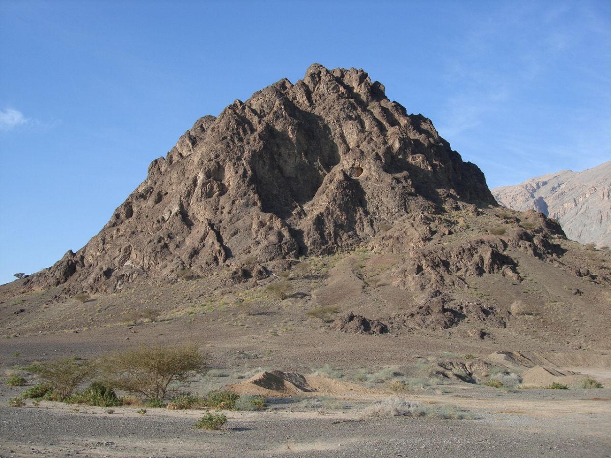
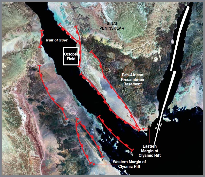
• The presence of basic igneous and metamorphic minerals and rock fragments suggests that surrounding basement terranes (Fig. 4B) were exposed, eroding and acting as a source of siliciclastic material,
• a series of wadis (eg. Wadi Baba, Wadi Araba and Wadi Feiran (Fig. 4B) are possible loci of sediment point sources;
• Wadi Araba (20km north of ET-A3; Fig. 1A) may have introduced large amounts of sediment into the rift during relative sea level fall. The axial flow of siliciclastic material would be confined to the fault block troughs. However, the distance of Wadi Araba suggests that is not a source of coarse-grained siliciclastic material;
• Wadi Baba and Wadi Feiran are closer siliciclastic sources and have the potential to feed coarser siliciclastic material via submarine canyons and relay ramps between extensional faults. Both mechanisms allow siliciclastic sediments to bypass carbonate producing areas and;
• Siliciclastic material may also be sourced from pre-rift sediments exposed in cross faults cutting fault blocks caused by the break-up of the Suez margin.
CONCLUSIONS
Tectonics and palaeogeography controlled sedimentation patterns which determined the aerial distribution and degree of development of reservoir quality. Such a predictive model should enable more accurate exploration for good quality reservoirs.